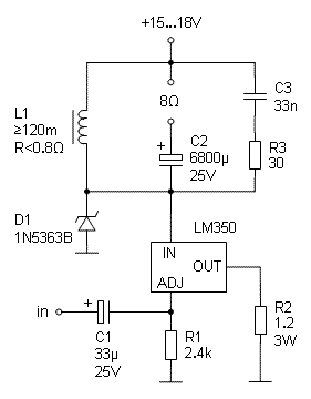
Single-Ended Regulator Transconductor (SERT) Amplifier
A Really Simple Class-A Power Transconductor
Here is a simple way to implement a current-output amplifier for music listening by using just a single voltage regulator as the active device. The design delivers 4 W sine power into 8 Ω load in class-A operation with very decent distortion.
Operation
The V/I conversion is performed by a 1.25 V voltage regulator LM350, whose output voltage and current follow the voltage applied at the adjustment pin. Since only a small DC current (50 uA) flows out of the ADJ pin, the current taken in by the regulator in practice equals the current through R2, consisting of a direct component of 1.15 A and a signal component that is simply Vin/R2. The quiescent current is conducted by the choke, L1, while the signal current passes through C2 to the load. The idling power is 17-21 W, depending on the supply level, and dissipated mainly by the regulator and R2. The zener diode, D1, protects the regulator against voltage peaks, that may arise from overdrive or disconnected load. The shunt network R3-C3 is needed to reduce the voltage gain at ultrasonic frequencies where the load is usually strongly inductive.
Since L1 is meant to establish high impedance at the operation frequencies, only a small fraction of the iron core distortion of the coil shows up in the load current. Likewise, since C2 only stores a small DC voltage (the voltage drop in the resistance of L1) and doesn't act as a filter, possible nonlinearities of C2 cannot significantly affect the current, that is determined by the regulator.
Frequency Scaling
The 120 mH choke coil has to be wound by oneself which is the most laborious part of the construction. However, in cases where low frequencies are not handled by the amplifier, the values of L1, C1 and C2 can be scaled down in inverse proportion to the needed low frequency limit. For such use, suitable coils for L1 can be found ready-made.
Performance
The low-frequency band limit is mostly determined by the choke inductance; with the value given and with 8 Ω resistive load, the response is 1 dB down at 22 Hz. At the high end, the -1 dB point is found above 100 kHz.
Measured total harmonic distortion into 8 Ω load (with unregulated supply) is shown below at 1 W and 4 W levels.
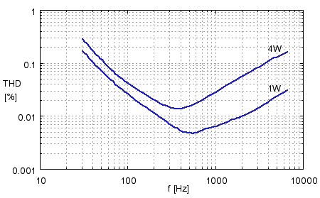
The THD is very acceptable yet at the rated power, remaining below 0.1% from 60 Hz to 3 kHz. The rise at low frequencies is due to the choke inductor, while at high frequencies the source is the regulator itself. Both the 2nd and 3rd harmonic contribute to the distortion. (Measuring above 6.6 kHz is not relevant, as the 3rd harmonic goes beyond the hearing range.)
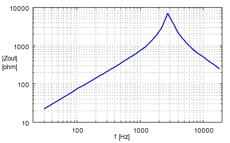
Measured output impedance is seen below. Below 1 kHz, the impedance is directly proportional to frequency (inductive) and determined by the choke inductance. At high frequencies, the impedance is determined almost solely by C3 and is capacitive. Only in the bass region, where high impedance is not so necessary, the magnitude falls below 100 Ω
The input sensitivity is 0.85 V, and the transconductance is simply 1/R2 = 0.83 A/V. The input impedance equals R1 (without volume pot).
Construction of the Coil
The choke inductance needs to be more than 100 mH to present high enough impedance also in the bass region. At the same time, the distortion due to core nonlinearity and also the DC voltage lost due to the bias current should be kept minimal. This requires a middle-sized laminated steel core with a suitable air gap.
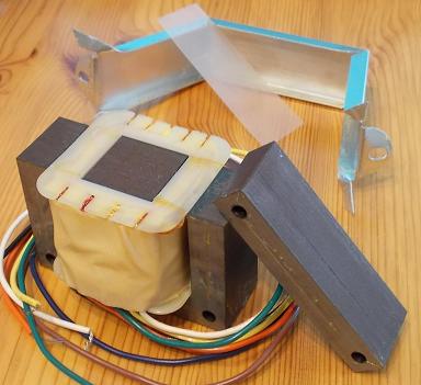
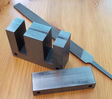
Nowadays, transformer cores are not sold separately, so one has to disassemble an existing transformer where the E and I core parts can be separated. This is only possible with some output transformers intended for single-ended tube amplifiers. Here is used a commonly available Hammond transformer of type 125ESE. The wire length needed for one coil is about 40 m; and a suitable conductor diameter is 1.1-1.2 mm.
The steps are as follows:
1. Disassemble the steel frame surrounding the transformer and separate the E and I core pieces. Open the metal folds under the bottom to unlock the frame (some sharp tool may be needed) and push a screwdriver under the frame to open it. Then, knock asunder the E and I core blocks and remove the thin plastic between them that formed the transformer's air gap.
(It is somewhat weird that the manufacturer uses here a steel frame, that to a great extend magnetically shorts the air gap in the side pillars and thus also causes unnecessary flux saturation in the relatively thin frame metal. This also prevents us from using the frame in this project.)
2. Detach the coil bobbin from the core. This can be done with a suitable putty knife. The bobbin is only weakly fixed to the center pillar.
3. File the air gap surfaces plain and clean. Use a flat file, and with controlled lengthwise movement level the gap surfaces so that they become almost wholly clear. This also increases the inductance. Take care to apply pressure only so that the surfaces remain flat and perfectly aligned.
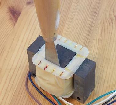
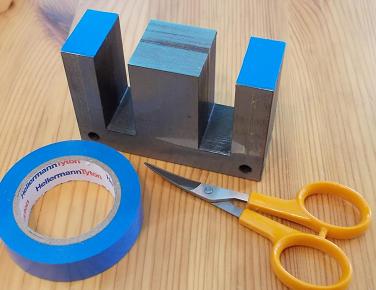
4. Place material layers of 0.3 mm thickness on the side pillars to form the magnetic gaps. No layers are needed on the center pillar. The gap in each pillar has to be close to 0.3 mm, giving a total gap length of 0.6 mm in the entire magnetic flux path.
The 0.3 mm thickness can be accomplished by using three layers of ordinary copy paper (usually they are 0.1 mm, but check first) or two layers of electrical tape that has a specified thickness of 0.15 mm (0.14 mm is still ok). See to it that the gap material does not extend over the edge on the screw sides where the fixing braces come.
5. Empty the coil bobbin from all wires. A hacksaw can save much labor here, but be careful not to cut the body of the bobbin. After emptying, the rectangular edges of the bobbin body can be rounded a little to facilitate the winding of the first layers.
6. Wind 250-260 turns of 1.1-1.2 mm wire side by side on the bobbin. This asks some patience and hand skill, as the wire is rather stiff and the layers must lie maximally flat in order to fit the turns in the core window. (Note that the overall diameter of the wire is greater than that of the conductor.) The bobbin accommodates at least 29 turns in one layer, so the last turns have to be on the 9th layer. Reserve enough time, for winding one coil tightly by hand is a matter of hours. Keep a suitable object at hand to press the turns down where needed.
Thinner wire can be used but at the expense of increased DC voltage loss.
7. Put together the parts using braces made of aluminum or other rigid and nonmagnetizable material. (Suitable aluminum profiles are widely available.) The screws can be ordinary (magnetizable) ones. Make sure that the coil bobbin, that may have expanded a little, does not lift the top piece (file if needed). Also, press the core parts towards each other while fastening the screws to ensure that the gap length remains as determined.
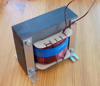
The coil shown below contains about 250 turns of 1.2 mm wire and has an inductance of 120 mH with a DC resistance of 0.61 Ω.
At the 1.15 A bias current, the flux density in the magnetic circuit will be about 0.65 teslas. This leaves yet enough room for the AC current component, that is also significant at the lowest frequencies.
Note: This kind of coil makes in itself some audible noise when passing AC current. The noise is noticeable at high frequencies and is comparable to the direct sound radiated from phono cartridges. The reason is a phenomenon called magnetostriction in which the core material expands and contracts due to its turning magnetic dipoles. The same effect is also observable in output transformers, especially when they conduct a DC component. The regulator also generates some audible vibration.
Implementation
The component count is so low that a printed board is not necessary. Below is shown a tweeter version of the amplifier assembled on a piece of turret board. The connections become evident from the pictures.
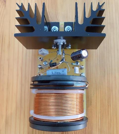
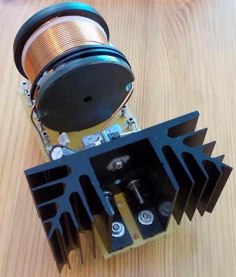
The choke coil seen here is 10 mH and 0.48 Ω. The heat sink shown is just adequate for 15 V operation in good ventilation but not necessarily ideal for 18 V. The regulator's tab (output) is electrically connected to the heat sink via the screw.
Power-on Muting
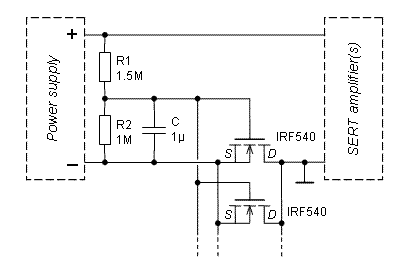
The turn-on transient can be suppressed with a MOSFET switch inserted in the negative supply rail, as shown below. The MOSFETs open softly in about half a second after turn-on, and thereby prevent the 'thump' sound from being generated. Only a weak 'nap' may be heard when the regulator becomes active.
Two parallel fets are shown here, but more can be added to minimize the voltage dropped in them. The on-resistance of the IRF540 is about 40 mΩ. Use at least as many fets as there are channels to be fed. No heat sinking is needed. (Note that the signal ground has to be on the amplifier side.)
Volume Control
If a volume control is needed, a 10 kΩ potentiometer can be inserted in a normal fashion between C1, the ADJ pin, and ground. R1 should then be increased to 3.3 kΩ. Using the potentiometer has an additional benefit that the quiescent current is reduced by 100 mA when the volume setting is down.