Class-A Transconductance Power Amplifier
Making Use of Adjustable Voltage Regulators
This is a new kind of transconductance (current-output) amplifier principle that employs standard adjustable voltage regulators (LM317) as the output devices. The operation of the 3-pin voltage regulators in controlled current-source configurations is described here (the last section). The amplifier presented is capable of delivering a good 25 W into 8 Ω load in class A. The operation is bridged which on current-drive remarkably improves the efficiency of Class A relative to one-sided feed or voltage drive. Only single +30 V supply voltage is needed.
Though the sonic differences between current and voltage driving of speakers are orders of magnitude greater than possible differences between the operation classes, this scheme should be quite ideal for those audiophiles who have reservations about class B or overall negative feedback. Though the regulators in themselves are feedbacked devices, the load applied to them remains always resistive.
Operation
Two pairs of LM317:s form the current-output stage, that has a quiescent current of 1.7 A. The LM1875 is used to generate the background potential for the load but has no effect on sound quality since the load current is solely controlled by the regulator stage.
The MC34072 op-amp with the NPN BC550C act as a unity-gain buffer to drive the lower regulators with a signal voltage and, at the same time, form a voltage/current converter to drive the upper regulators with a signal current. The upper regulators make up current-controlled current sources while the lower ones are connected as voltage-controlled current sinks.
R5, P1, and R6 supply the needed bias current for the NPN. With trimmer P1, one can null direct current flowing to the load.
The LM1875 operates as an inverting amplifier making the two load potentials move symmetrically in the bridged configuration. The gain is not exactly -1 but -1.15 to make maximal use of the voltage headrooms available. The plus terminal of the speaker is connected to the right-hand side.
C6 & R14 are for stability assurance, like in the other transconductor topologies. The circuit hasn't shown any signs of oscillation with any loads from a short to inductive wiring and voice coils and with varying signal and supply levels.
The frequency range of the regulators used is also well sufficient for audio amplification purposes. With the circuit above, the response is less than 0.3 dB down at 20 kHz. The lower cut-off frequency is determined by C1 with R3 and R2.
Why are two regulators working in parallel, instead of using just one, e.g. LM350, that could handle the whole current? The reasons are:
- The power dissipated is too much for a single TO-220 package, the TO-3 versions being very costly.
- The output noise generated by two regulators is, in principle, 3 dB lower than from a single device. (As the noise sources are uncorrelated.)
- The LM350 exhibited a little higher distortion, at the required current levels, than the LM317.
Performance
- Output power:
into 8 Ω: >25 W
into 16 Ω: >15 W
- THD @ 1kHz:
@ 25 W: 0.05%
@ 1 W: 0.045%
- SNR @ 25 W (up to 20 kHz, unweighted): 90-91 dB
- Quiescent power: 54 W
- Efficiency @ 25 W: 32%
- Input sensitivity: 0.70 V
- Input impedance: 18 kΩ
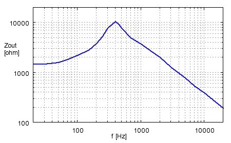
Output Impedance
The measured output impedance of the amplifier is seen below. Up to about 4 kHz, the magnitude ranges from 1 kΩ to 10 kΩ, sloping to 200 Ω at 20 kHz. Above 400 Hz, Zout is quite inversely proportional to frequency (capacitive) and is mostly due to C6. At lower frequencies, the regulators' line regulation properties become the limiting factor.
Low-Power Mode
A nice and economic feature with this type of transconductor is yet that it can be used in a low power mode when listening only at moderate levels. By switching resistors R11 and R13 out, the regulator bias current and hence power consumption drop to a half while the amp still operates normally but only with halved current capacity (and sensitivity). This also reduces the background hiss though it is hardly audible at normal distance even in the full mode.
If this option is implemented, a 330 Ω resistor should be added in parallel with R13 to draw a minimum current from the regulator during the cut-down use.
If 7 W is sufficient for output power, the rightmost regulators with their associated resistors R6, R11, and R13 can be wholly omitted. R5 should then be reduced to 27 Ω, and the supply voltage may be lowered to 20 V.
Muting
Like conventional ones, current-output amps also usually need some muting of the on/off switching thumps, this design being no exception. However, in current-drive this can be done by shorting the speaker instead of disconnecting. Bulky and themselves sound making relays are not necessary, for the task is best performed with power mosfets.
The circuit below is suitable for this. When the drive transistor is in off state, the mosfet gates get the supply potential, keeping the fets conductive with low on-resistance. When the transistor becomes conductive enough, the mosfet gates (and sources alike) are pulled close to the ground potential which turns the fets off, thus releasing the speaker terminals. R1 with C provides a turn-on delay that keeps the muting on during the power-up process. When the supply is falling, the BJT must be turned off (and the fets on) without delay. This is accomplished by discharging C rapidly through the diode.
The control circuit connecting to the gates can be common for all channels. When using other voltages than 30 V, only R2 needs to be altered, in order that the threshold level remains at about 80% of the full voltage.
Two mosfets are needed in series connection because their internal drain-source bulk diodes prevent them from being used bidirectionally. (For some odd reason, nobody manufactures power mosfets where the body (substrate) could be freely accessed.) The 16 V zener diode protects the gates from any overvoltage and also keeps the common source point at a defined low potential during use.
Board
A strip board layout for the amplifier is shown below (without the muting circuit). Only a few jump wires are needed. The two arcs denote power supply jumps placed on the copper side. All tracks carrying load currents should be tinned to enhance conductivity.
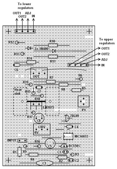
For rigidity, the supply voltage and speaker are best connected with 3-way screw terminals (the third way being left dummy).
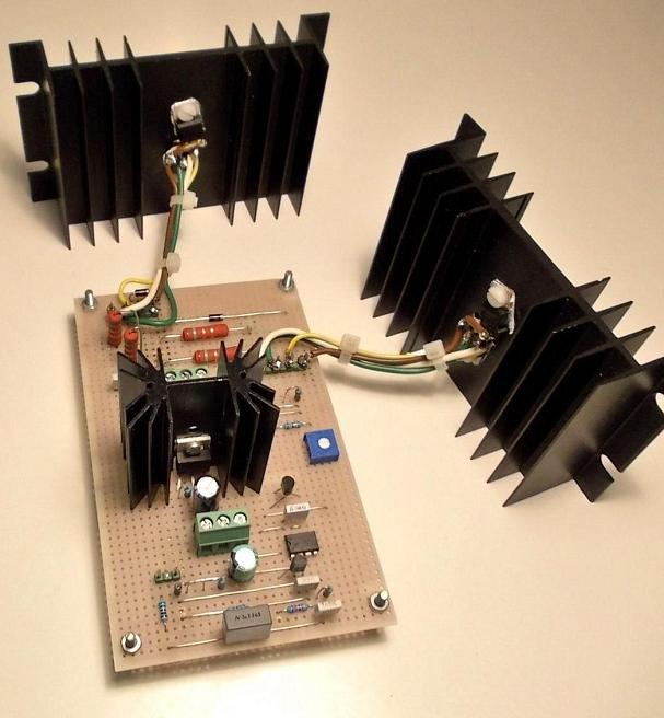
Each pair of regulators can be attached on a common heat sink even without mica washers if the blackened surface is free from scratches and hence insulates well enough.
Powering
A simple unregulated basic-type power supply is enough. For two-channel operation, the following component values are suitable:
- Transformer: 200 VA, 24 V (two 12 V coils in series or 24 V coils in parallel)
- Rectification bridge: 8-10 A, with heat sinking capability
- Capacitors: 2 pcs of 10 000 uF/50V electrolytics in parallel
- Primary fuse: 2 A, slow
Notes
Do not replace the MC34072 with the popular TL07_ amps or others; they will not work here because of their input range limitation. Also, do not use the single package MC34071, as it lacks input protection.
For R10 - R13, 2 W is needed, but 3 W is more recommendable.
For continuous use, the heat sinks should be larger than those in the picture. Do not use any soft thermal pads, as they are totally unsuitable for TO-220 cases, are inferior to mica and can even warp the tab when tightened.