Clean-Current Full-Range Speaker CCS-7
This novel, long developed speaker concept and project enables one to get into enjoying the sound quality level of current-drive, at least for the most part, using yet only a conventional low output-impedance voltage amplifier. It is a full-range speaker using Scan-Speak's bass/midrange unit 15W/8434G00 with series impedance and aided with a step-up transformer. The bass resonance has been damped by a novel, sealed, back-loaded, folded channel, that is tuned by positioning of fibre sheets. The air volume of the enclosure is 7 l, of which the channel takes 5 l. Instead of the channel, it is also possible to use electrical RCL damping with a bare sealed box of 5 l.
Diagram
The schematic of one channel is shown below. The transformer operates here like in current mode, that is, the actual series resistors, R1a and R1b (3 Ω jointly), have been placed on the primary side. The device is a commercial 2x12 V, 120 VA toroidal power transformer with its 12 V windings connected in series as the primary and 115 V windings in parallel as the secondary.
Why a power transformer? Because there are no commonly available audio transformers of the needed size that come anywhere close to the suitable turns ratio (here 1:4.4), the price is affordable, and in toroidal transformers the high permeability and saturation level of the grain-oriented steel can be fully exploited (as is done in power transformers) to maximize inductance and hence to minimize the magnetizing current taken by the transformer.
The resonance networks R2-C1-L1 and R3-C2-L2 are used to establish more series impedance for the mid and high frequencies that need to be attenuated to rectify the frequency response, due to front panel diffraction and the cone's 6 kHz boost. Capacitors have to be of plastic dielectric and the coils air core with 1 mm wire, so that their DC resistances fall near the values marked in the figure and used in the design.
Operation Point
The turns ratio of primary to secondary is 1:4.4 (the ratio of nominal voltages normally differs from this a little), so the transform ratio of impedances becomes about 19, and thus the speaker impedance of 8 Ω appears on the primary side as 0.42 Ω, nominally. In series with this primary load, there is then always at least 3.7 Ω resistance, consisting of resistors R1, the coil resistance of L1 (0.3 Ω), the transformer's winding resistances (as reduced to the primary), and also of the input cable, that should be short. Therefore, observed on the primary side, the series impedance seen by the load is (nominally) 9-fold relative to the load impedance (0.42 Ω) itself (naturally the same would follow also by considering the issue on the secondary side), so the attenuation of the driver's harmful EMF currents will be, in principle, already 20 dB
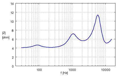
The measured load impedance, as seen by the amplifier, is shown below. The minimum comes out as 4.1 Ω, which should be yet easy for a normal amplifier. The small rise at 90 Hz reflects the resonance peak of the speaker itself. The elevations at 1.1 kHz and 6 kHz have been set to attenuate the usual prominence caused by a box-type enclosure and the break-up frequencies of the driver used.
The amplifier's output impedance, usually given at 1 kHz, should be about 0.1 Ω at most, so that it wouldn't affect the designed response at high frequencies either, where the output impedance usually rises strongly. Thus, tube amplifiers or standard class-D ones are not very recommendable.
With the impedance ratios used, 10% of the power fed by the amplifier ends up to the driver itself, the rest being consumed in the series resistances. The loss in sensitivity due to the series impedances is thus 10 dB, as a starting point. Here we should note, however, that quality amplifiers can often deliver into 4 ohms almost double power (i.e. +3 dB) relative to into 8 ohms, wherefore the maximum level available is just a good 7 dB lower than if the driver were fed as such, conventionally encased. Additionally (as will later appear) the enclosure principle used here raises the operation sensitivity of the driver at low frequencies yet by a good 2 dB relative to conventional voltage use, leaving us in practice with a net sensitivity loss of only about 5 dB which shouldn't be any problem, minding the maximum undistorted power level of this size drivers.
With the resistor power ratings and the transformer shown, the speaker may be used, on music, with an amplifier that delivers at most 300 W into 4 ohms since, in normal use, the average (heating) power is but a fraction of the nominal output power. The transformer needs to be of the size chosen since, though the power transferred by it stays yet far from the nominal, the nominal current of the windings (5 A for the primary), however, is, in principle, exceeded at 100 W input power (which thus doesn't happen yet with practical signals).
Transformer Nonidealities
The distortion introduced by the transformer is in practice so diminutive that in measurement it easily remains in the shadow of typical amplifier distortion; and, due to high inductance, the magnetizing current doesn't yet limit the bass response at all (unlike in tube output transformers). In the model chosen (MCTA120/12), the stray inductance is also yet small enough, so that it doesn't significantly limit the range at the top end.
Also, there is no danger of saturation of the transformer core, for the magnetizing current is proportional to the transformer's operation voltage, and even at the 300 W input level, the primary voltage will be only about 5 V, that is, a good 20% of the nominal value (at 50 Hz), so the magnetization works yet at a good distance from the saturation region.
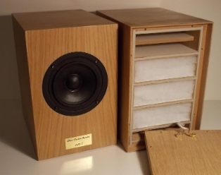
Transmission Line Enclosure
Below are shown the drawings of a closed transmission line enclosure with a screw-openable back wall, managing the damping of the driver's fundamental resonance. The cabinet consists of a 2-litre chamber attached to a little over 1.5 m long, 9-layered channel, which, when suitably filled, forms the acoustic load resistance needed by the driver for the management of the bass resonance and optimization of the response. Besides, thanks to the interior walls, the cabinet is excellently rigid.
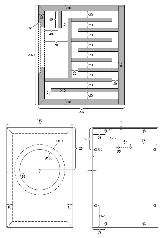
All internal dimensions are whole cm:s, the thickness of all internal plates is 1 cm, and the channel thickness is 2 cm everywhere. If there is no exact 1 cm board available or makable, it is important that the channel thickness and chamber volume are kept precise.
The damping wadding is inserted in the channel slots via the released back wall, and the plate ends adjacent to it must be justified and sealed well. Special attention must also be paid to the tightness of the other plate seams, for even a minor hair leak e.g. from the chamber to the channel alters the functioning of the cabinet essentially. Joints should always be secured, for even when hiring a professional maker, there can be left gaps, depending on assembly methods. Possible weak points must be blocked by some substance that withstands the pressure alterations. (Silicone is not good.)
The wire is here designed to be drawn directly via the upmost slot, but it can also be drawn e.g. through a hole made in the chamber floor and the downmost slot if there are means for reliable sealing of the hole.
Filling
For damping material suits Sonofil polyester fibre that is available in about 1-in thick sheets. From the sheets are cut 14 cm x 16 cm pieces, just fitting to the slots. Some of the pieces are yet cut in two in the thickness direction, to enable the most suitable degree of filling.
The channel slots are filled with as even as possible placement, according to the following table (slots numbered from the top 1-9):
1: empty
2: empty
3: 1 layer of Sonofil fibre
4: 1½ layers
5: 1½ layers
6: 2 layers
7: 1½ layers
8: 1½ layers
9: empty
In slot 8, which is longer, is also used same size (14x16) pieces, placed next to the back lid, like the others.
The greatest effect on the frequency response is produced by the filling degree of the front end slots and the least by the back end ones, that affect mostly the lowest frequencies. The damping material in the chamber also shapes the response a little.
The wadding sheets exhibit a little quality variation at least in the thickness. Therefore, to ensure good reproducibility, it is advisable to leave the thickest and thinnest ones unused or use them only in the back end slots, where the effect of these differences is in practice no more seen.
Pushing the wadding evenly into the slots is easier if the plates have some smooth coating, instead of bare MDF board.
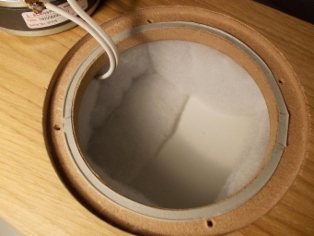
Chamber damping has been done by three Sonofil pieces: one 7 cm x 40 cm strip bended in U shape, covering the bottom and side walls, one 14 cm x 16 cm piece (like in the channel), folded in two, in the top nook, and one piece of the same size but half thickness to cover the bottom and part of the back wall. At the channel mouth must be left some empty space. Pictures below clarify the filling and the enclosure structure.
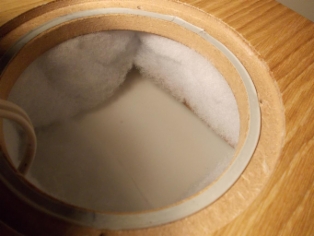
Responses
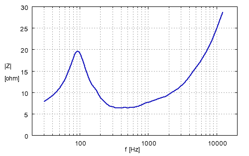
With the instructions above, the impedance of the mere encased driver will be as shown below. The result, measured at 50 mA current, resembles the curve generally obtained with a sealed enclosure, but the resonance peak (92 Hz) rises here only to about 20 Ω which gives an expedient response. When the channel is empty, the impedance is totally different due to standing waves, containing several sharp peaks.
In room conditions, the acoustic responses of low frequencies cannot be well measured at normal distances directly, due to aberrations introduced by standing waves and other room effects. Therefore, these measurements have been performed at close distance, the microphone diaphragm at about 1 cm from the dust cap. The up-close measurement causes, however, that the baffle step effect, that is normally present in the far field and weakens low frequencies by 6 dB, doesn't show up, but the result instead corresponds to a condition where the speaker's front panel would be extended to infinity. Based on the results it is, however, rather easy to evaluate the actual response that includes the baffle step, for at low frequencies and with box-like enclosure, the effect of the step is well known and monotonic.
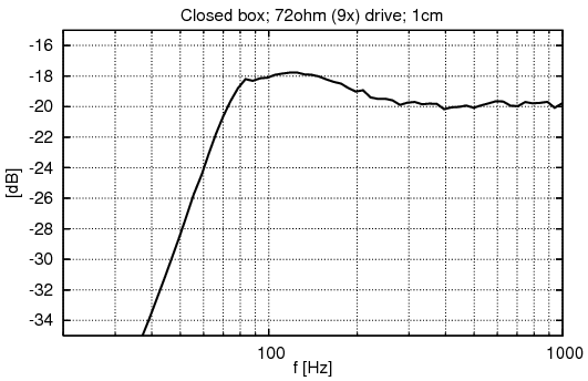
Figure below shows the up-close-measured response of the mere encased driver at about 200 mA current and 72 Ω driving impedance which corresponds to the impedance seen by the driver in the final transformer circuit at low frequencies. The acoustic resistance produced by the channel damps the response peak of the current-driven speaker, occurring around 100 Hz, to about 2½ dB in height; and in addition, the reflections arriving from various parts of the channel yet boost the 200 Hz region by a good 1½ dB, the effect being still somewhat observable up to 300 Hz.
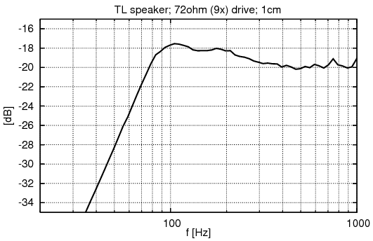
This is quite an ideal shape of response, for when we add to this the decrease of low frequencies introduced by the baffle step in the far field, which in this case lowers e.g. the 100 Hz point by about 5 dB relative to the 1000 Hz area, we see that about half of the needed baffle step compensation (which generally applies to all encased speakers) has already been covered owing to the sensitivity increase brought by the channel and current-drive, i.e. the need to attenuate high frequencies electrically is much lesser than generally otherwise.
The roll-off rate of the bass is about 13 dB/octave which quite corresponds to 2nd-order filtering, like in general in sealed enclosures. The -6-dB frequency limit will be here about 64 Hz which is rather suitable for this size driver when the cone is the only radiator.
The same enclosure suits for use also on pure current-drive, but then the optimal channel filling is a little different.
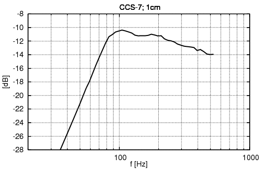
The up-close response, up to 500 Hz, of a finished speaker with the adapter unit is seen below. The difference relative to the former is only a steepened decrease in the hundreds of hertz region, for the final baffle step compensation. In practice, the baffle step drops the response below 100 Hz by a scant 4 dB, relative to 500 Hz, wherefore the response in the far field becomes fairly flat.
The next figure shows the final response above 500 Hz. The measurement has been made at 50 cm distance (where the baffle step is already almost fully developed) and 8º upwards from the center axis, representing a practical listening direction. The response, compensated by the series impedance, stays within ±2 dB limits almost all the way up to the high limit where the 6 dB attenuation comes along at 14 kHz or so.
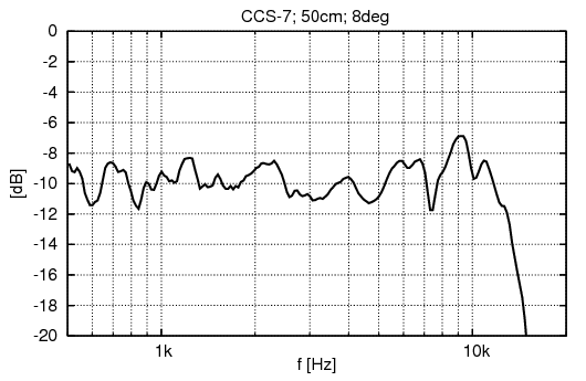
If desired, the treble level can be increased a little in the 6-10 kHz region by raising C1 to 8.2 µF.
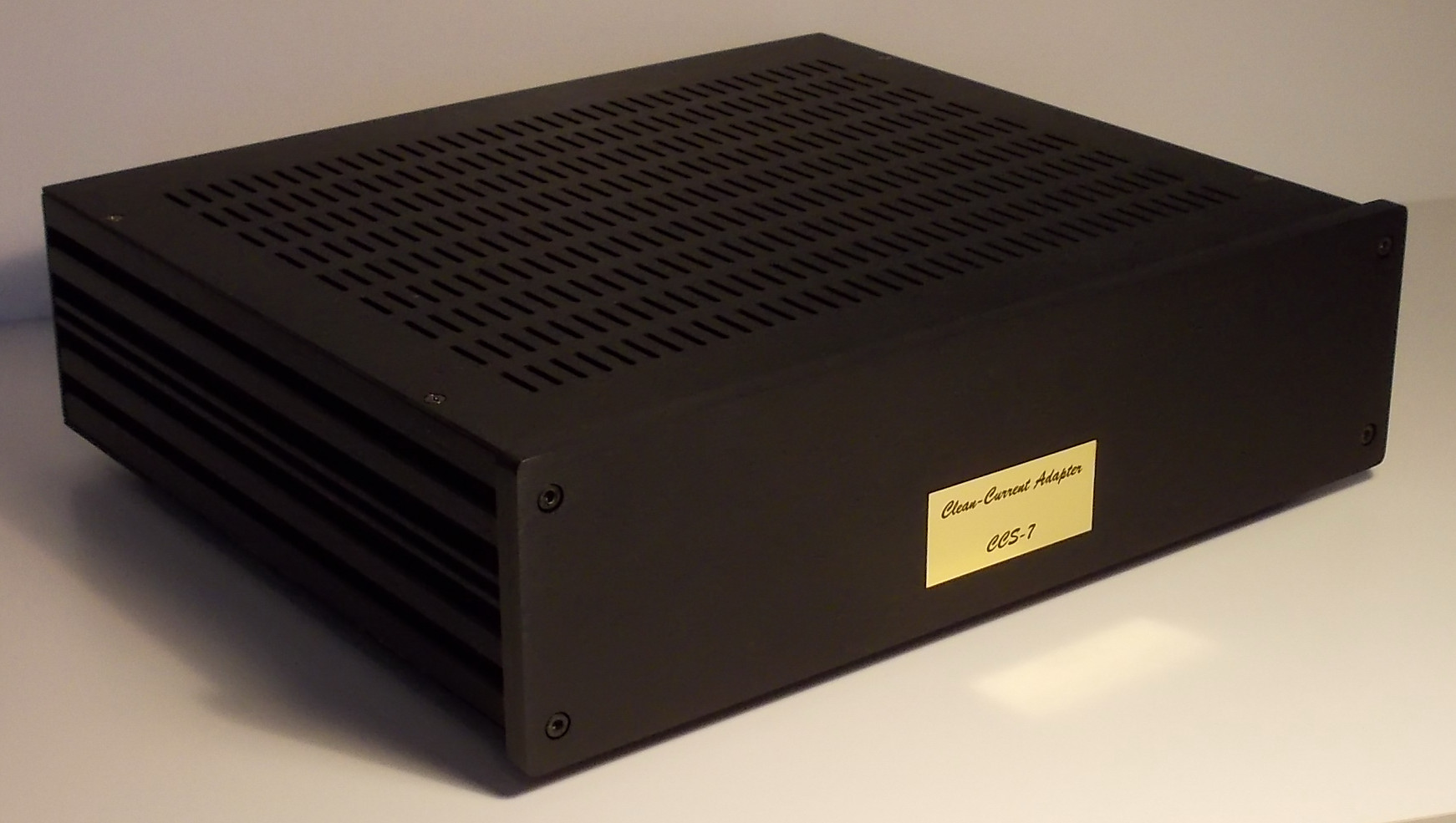
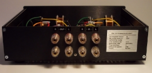
Adapter Unit
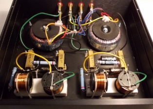
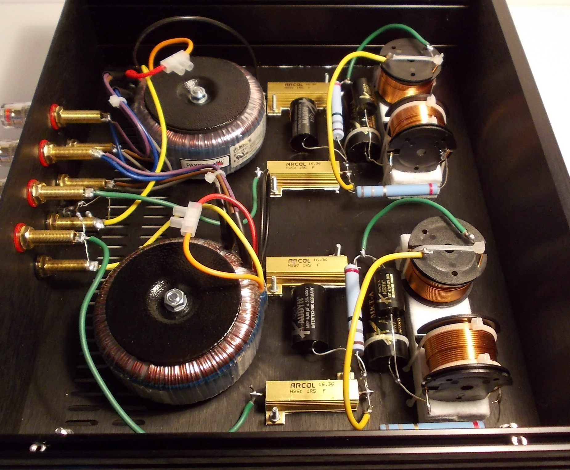
The transformers, series resistors, and filtering components need a well ventilated aluminum case, with a perforated top cover. Using a case smaller than this is not expedient, for in addition to cooling, one has to also provide sufficient spacing from the air core inductors to the metal surfaces of the case. Component layout and wiring for two channels is found out in the pictures below.

By dividing the series resistance R1 in two parts, there is achieved here, besides the desired resistance value, also evener distribution of heat in the bottom plate and some leveling of tolerances.
The coils have been positioned on a base made of stacked pieces of self-adhesive felt plates. In this way, one can get at least 2 cm of distance from the coils to all case surfaces which, according to measurements, is enough to keep losses and the inductance unchanged. The coils have been attached to the bottom by cable ties, like also C2. Using screws near the coils is not expedient.
To improve cooling, the joints between the bottom and side panels have been coated with thermal grease, and a third screw has been added in the middle. To support the bottom plate, it has yet been attached to the back plate with an L-bracket, by whose screws and soldering lugs there has also been secured electrical contact between the plates. The contact of the back plate with the side panels has been secured as well by using the bright screws included and by peeling the oxide layer under the screws.
R4 is connected separately from both channels to the above-described chassis contact while the secondary side of the transformer is left floating.
Sealed Enclosure Alternative
If building the channel is considered too demanding, a mere sealed cabinet may also be used, with the front panel kept similar. For the gross interior volume, 5.0 l is a good fit. Then, however, the fundamental resonance of the speaker must be damped by an RCL chain connected across the driver, suitable values being:
R = 22 Ω, 5%, 10 W
C = 57 µF (47+10), 5%, 150 V
L = 36 mH (18+18), 5%
R is here the total resistance of the chain, also including the DC resistances of the coils. In practice, it is best to choose a 22-ohm resistor, across which is added a resistor of greater resistance (and lesser wattage) such that the sum of the resistances of this parallel connection and the coils equals 22 Ω. For the sake of cooling, it is well to place the resistors outside the speaker enclosure, e.g. with their own binding posts or to the other pair of a bi-wiring terminal.
The cabinet is entirely filled with cotton cloth, that is best obtained from sheets. The cloth is rent into roughly 20 cm wide shreds, that are squeezed into tangles and crammed everywhere with modest force, leaving, however, some empty space around the driver. (Cotton cloth is the most effective practical material in reducing an stabilizing the mechanical Q value of the system.)
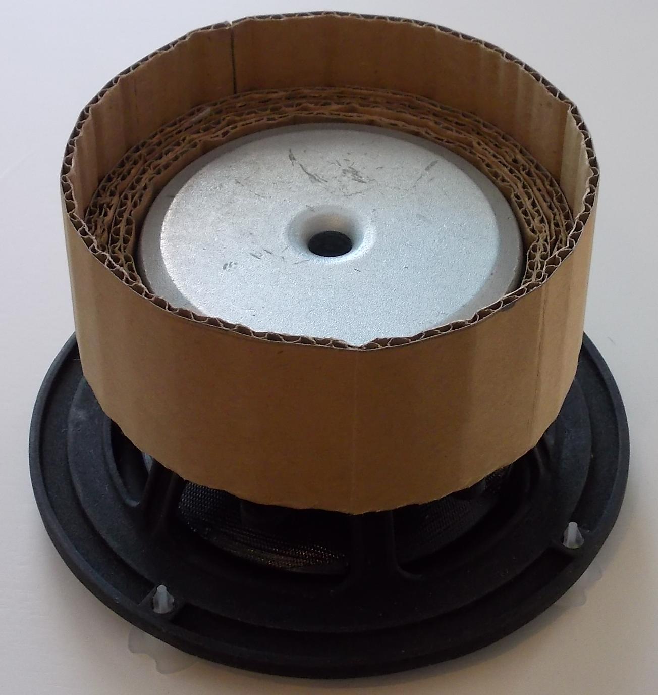
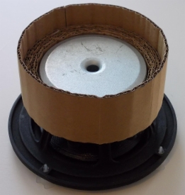
Migration of the cloths too close to the driver can be prevented by gluing around the magnet a few layers of corrugated fiberboard such that this guard ring yet just fits from the mounting hole (picture below). The fiberboard itself doesn't block the driver, for the channels conduct air well through. The outermost layer may yet be extended a couple of centimeters behind the magnet, so that the rear vent also stays free.
The up-close measured response of the mere encased driver, at the 72 Ω driving impedance, is seen below. The response obtained is almost identical to that above with the transmission line enclosure. Only the 200-300 Hz region is left slightly lower, as there is not the lift brought by the channel. Also, the roll-off slope is here somewhat greater: about 15 dB per octave.
If desired, the 100 Hz region can be fine-adjusted by changing the value of R. A higher value elevates this point a little and vice versa.
It is well to know that – unlike in corresponding active compensators – the resonance frequency and Q value of the RCL chain DON'T NEED to be coincident with the respective values of the speaker, for the operation of the network is not based on such exact cancellation. Instead, the most optimal result is generally achieved when the frequency of the RCL chain is about 20% higher than the resonance frequency of the speaker and the Q value is little over 1, almost independently of the speaker Q. Thus, the tuning is by no means particularly sensitive to parameter variations and also not more sensitive than an ordinary reflex alignment.