Speaker Project CS-12
 In the following is introduced a 12-litre closed-box 2-way speaker project for current-drive (Current Speaker 12). This design relies on active resonance and baffle step compensation and is therefore well suited for use with the presented transconductance amplifier. Detailed design principles and process with the optimized driver models and simulation results are presented in section 11.4 of the book.
Drivers
In the original units, the bass-mid-frequency region has been served by a Vifa driver P17WJ-00-04, whose diaphragm is of filled polypropylene. Afterwards, the manufacturing of this driver has been discontinued. However, in stead can be used type PL18WO09-04 (also by Vifa), whose diaphragm is of coated paper and which corresponds, both in frequency response and impedance, well enough to the device on which the design is based.
After Tymphany acquired Vifa, the PL18 alternative has also been discontinued, as all of this renowned brand. As a substitute, Scan-Speak 15W/4434G00 is also quite well suited though it is a 5-incher and has a higher Qm value than the Vifas.
The tweeter used in the model units was Scan-Speak's D2905/990000, that has a 28 mm textile dome, a rear chamber, and a gradually-sloped aluminum flange. However, as the driver is quite pricey, it can be substituted by D2905/970000, which is otherwise similar in structure but has a conventional flange. The somewhat lower sensitivity of the D2905/970000 may even match better with the mentioned woofers in the 2-3 kHz region.
Circuit
The schematic, shown below, involves nothing special except the tweeter's shunting network, whose resonant frequency is set close to that of the tweeter. The network is used to flatten the dip introduced in the total frequency response due to the fact that in this resonance region (around 500 Hz) the phase responses of the drivers inevitably come at 180º from each other. Due to the rather high Qm value of the tweeter used (ca 3.8), the response dip would be without the shunting network about 7 dB.
Half of the mentioned 180º stems from the phase difference of the currents and the other half from the resonance-induced phase lead of the tweeter, that is characteristic to all moving-coil drivers. (The problem also occurs as well in voltage-operated loudspeakers, even though the issue is not generally recognized, but the upper-frequency driver is thought to behave flawlessly somewhere down to its resonant frequency.)
Current Division
The simulated current amplitudes are shown below. The crossover point has been set to 1.5 kHz in such a way that the currents equal unity, that is, are unattenuated, at this frequency. Then, the phase difference between the currents will be close to 120º, instead of the usual 90º target.
The bass-midrange driver's current (Il) rises, at highest, a good decibel above the applied current, and the tweeter's current (Ih), in turn, a scant decibel. With a tuning of more than 90º, overshoots are inevitable but stay here yet moderate.
Current through the shunting network (Ir) is appreciable mostly only in the tweeter's resonance region, so it doesn't load the tweeter significantly in its operation range.
The crossover alignment has been made this tight for a number of reasons: Increasing the impedance of L1 and C1 increases the source impedance seen by the drivers, and the tweeter current stays in the stop-band sufficiently low, like also the bass-midrange current at the highest frequencies. (It is nevertheless safer not to use very high-powered amplifiers with this design.) Decreasing C1 also helps to curb the above-described response dip.
In the tweeter current, one can detect at 70 Hz a small prominence, that is due to the woofer's impedance peak. However, the use of the pole shifting equalizer, as incorporated in the presented amplifier, negates this rise because the total current of the speaker decreases in this region.
Filter Components
In practice, at least C1 has to be composed of several capacitors since the value does not fall close to commercial standard values. C1 and L1 should be quite accurate to keep the crossover filtering well controlled.
L1 is an air core inductor with DC resistance preferably in the range 0.4-0.5 Ω.
L2 can be even of thin wire because its resistance is not critical. R is just chosen so that the sum of the resistances becomes 22 Ω.
The target value of C2 depends a little on the tweeter's resonant frequency, that is best to be measured. If the frequency is somewhat below 500 Hz, an optimal value is 8.2 µF; but if the frequency is 500 Hz or over, 7.8 µF is more appropriate.
The coils L1 and L2 should not be situated close to each other, so that the ferrite of L2 would not increase the inductance of L1. To minimize the transformer effect, i.e. the mutual inductance, it is also good practice to orient the coil axes perpendicular to each other, as is also generally recommended. Further, if the speaker is going to be used on a steel stand, it is better not to situate the coils at the very bottom of the cabinet because a base made of magnetizing material can increase the inductance and losses of the coils.
Construction
Suggested cabinet dimensions, when using the D2905/970000 and PL18WO09-04, are given below. With 19 mm wall thickness (preferably MDF board), the internal volume will be 12 litres. For the front panel is recommended 22 mm thickness. The drawing also includes a bracing shelf that supports the back and side walls.
The front panel has been inclined backward to compensate the difference between the acoustic source points of the drivers in the listening direction, and even a little more to adjust the acoustic phase difference. The most suitable listening height is, with these dimensions, somewhat above the cabinet's top surface level.
The tweeter is embedded in the front panel's plane, but the woofer is not since thereby the inclination need can be reduced. To prevent the relatively thick front panel from obscuring the air flow of the woofer, the hole is best to be bevelled from inside.
With a 5.5-inch woofer, like the Scan-Speak 15W/4434G00, the hole center should be situated 2 cm higher than in the drawing.
The cabinet is filled tightly with cotton cloth, that is best obtained from sheets. This is for two reasons: It is the only effective way to reduce the noise pressure inside the cabinet and hence the passing of this noise through the cone at lower mid-frequencies. (So-called electrical damping does not affect anything in this region.) Secondly, cotton cloth is very effective in decreasing an stabilizing the mechanical Q value of the system; so there is less need for electronic equalization.
The cloth is rent into roughly 20 cm wide shreds, that are squeezed into tangles and crammed in with moderate force. One cabinet takes 4-5 single sheets, so it may be worthwhile to eye some offers.
Around the woofer is left, however, an inch of free space, minding also the hole in the center of the magnet. The cloth tangles hold in place pressing against each other, but it is nevertheless advisable to avoid turning the speaker front side down. To ensure that the material doesn't touch the woofer, some screws can be fixed inside around the hole.
For gaskets, one can use rubber rings that are cut to size from a sheet of about 1 mm thickness. The screw holes to the gasket are best made by an ordinary paper hole punch.
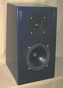
The front mask is most easily made out of plastic foam sold for the purpose; by attaching together, with elastic glue, two layers, of which the inner one forms only a frame. If desired, the mask can yet be thinned in the tweeter area by scissors. (The stripes visible in the photo are mask fastening stickers.)
As a stand, one can use even an ordinary step stool if the height is suitable. Actual speaker stands are generally too unstable with a load of this weight.
Equalization
The builder should preferably have some means to measure the resonant frequency and mechanical Q value of the woofer in its enclosure. These values can then be used to tune the pole shifting equalizer of the amplifier or a corresponding resonance leveling network.
The PL18WO09-04 has a free-air resonant frequency of about 40 Hz with a Qm of about 2.6. In the presented enclosure with the described filling, the final values should come out close to 62 Hz and around 2.2, respectively.
In this design, the baffle step compensation is also meant to be implemented actively, as done in the presented amplifier, for thereby the bass-midrange driver can be kept more purely in the current mode. Quite a similar filtering function can usually also be established by adjusting the bass knob of amplifiers.
When using the Scan-Speak 15W/4434G00 with equal enclosure, the resonant frequency will be of the same order, and the Qm value ends up somewhere near 2.5.
The Response
Below are shown the measured current frequency responses, taken at 2.5 m, about 15 cm above the top surface level of the model unit. The decibel scale represents sound pressure at 0.354 A current, at 1 m distance. The bass region has been measured separately from the near field.
The need for the baffle step compensation becomes well apparent from the results; and the remaining response dip in the 500 Hz region is quite negligible.
The prominence around 2 kHz stems from a mild unevenness in the drivers' acoustic phase difference, probably related to the chamber structure of the tweeter. In this region, the response can, however, be affected by adjusting the listening height. Using the flat-flanged D2905/970000 as the tweeter should also lower this region.
The attenuation in the side direction near the crossover frequency stems mostly from the increase in the bass-midrange driver's phase lag, in accordance with the minimum-phase nature, as the amplitude response falls off; and partially also from the changing of the acoustic source point difference.
The resulting Q value with the woofer employed comes out quite close to 1, so in this case it is almost a matter of taste whether resonance correction is any more needed.
It is advisable to use a carpet between the speaker and the listening place to attenuate floor reflection.