New!
Combo Attenuator
With this potentiometer-switch combo attenuator topology, it is possible to largely keep the benefits of both methods of volume adjustment without much of the negatives of either. The coarse level is set with a 6-position rotary switch (which are widely available and stocked) in steps of 8 dB, while the fine adustment is made by a compensated linear potentiometer in an 8 dB span, thus covering a total attenuation range of 48 dB.
Two design versions are presented: The 'unloaded' variant may be used when the load at the output can be deemed negligible, e.g. the noninverting input of an amplifier or anything above about 150 kΩ. The 'loaded' version is optimized for 70 kΩ output load, which may result e.g. from a balance potentiometer stage.
Tolerance variation (allowed 20%) of the potentiometer, P1, is compensated by choosing R1 according to the formula given, whereby the parallel connection of P1 and R1 becomes exactly 8 or 4 kΩ, so that high precision is retained also at the low end of the adjustment range. (P1' is the measured end-to-end resistance of the pot and must be known before R1 can be determined.)
The linerity of the adjustment curve (in dB) can be fine-tuned and channel balance improved by the trimmer pot, P2. The trimming range is 0.6 dB at the center of P1 travel, decreasing to zero at both ends.
The resistances shown are commonly available E24, 48, or 96 series values. In the chain R4-R9, all calculated values fall within 1% of these standard values.
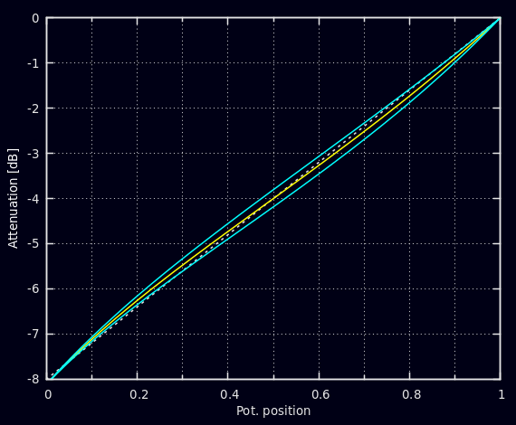
Attenuation of the pot stage vs. position is shown in the simulations below. The first plot shows the nominal behavior with best-fit trimmer setting (yellow) together with the effect of common +/-20% tolerance variation in pot track resistance (blue). It is seen that deviation from the ideal behavior (dashed line) is minute over the whole range, and pot tolerance can shift the curve only by +/-0.2 dB in the center region and naught at the ends.
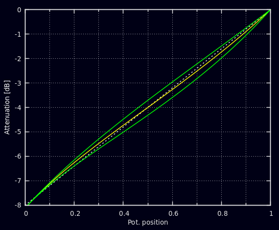
The second plot shows the span of the trimmer adjustment in green. Tuning can be performed at the center position of P1 by feeding the input e.g. by 1 V (AC or DC) and striving for 0.631 V (-4 dB) at the slide of P1 (with the stepped attenuator in place and preferably at the -8 dB position). If the original imbalance between channels happens to be more than 0.6 dB, it cannot be entirely countered by the trimmer, but nevertheless a great part of it.
In the loaded case, the switch position also has a minor effect on the curve, but this makes only +/-0.1 dB in the lower half of pot travel. (The simulatons are taken at -8 dB position.)
With the pot serving only 8 dB range, the effect of mismatches between the units of the dual-gang pot is greatly reduced, compared with the ordinary full-scale usage. Consider e.g. a tracking error of 10% of total track resistance, between the units, which is a realistic worst-case estimate for DIY purposes. Now, as the full span is 8 dB with linear behavior, this mismatch is able to introduce only 0.8 dB imbalance (before trimming). This is to be compared with the common imbalance of several decibels effected by conventional volume controls at low listening levels.
The minimum resistance introduced by the 'loaded' version circuit to the driving source is 3.5 kΩ (at 0 dB settings and P2 at 0 Ω). While this is less than usually, it shouldn't yet pose problems for any reasonable-quality line source.